Since Euclidean Space has no preferred origin or direction we need to add a coordinate system before we can assign numerical values to points and object in the space.
Two Dimensional Grid
If we want to specify a given point, in some two dimensional plane, we could overlay that plane with a grid, as follows:
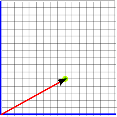
The x and y coordinates representing the point can then be read off the grid.
Usually the lines of the grid are orthogonal (mutually perpendicular). If the aim is only to have a method to uniquely give a pair of numbers to any point then orthogonality is not necessary and a skewed grid like this will work:
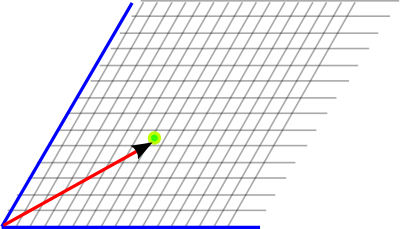
An orthogonal coordinate system does have useful properties and, as we shall see, thats what we usually use.
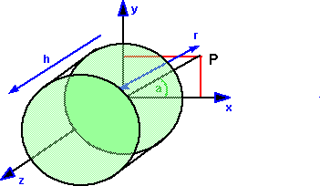
Sometimes there are advantages in using a non-linear coordinate system, such as circular coordinates, we discuss these here.
Three Dimensional Coordinates
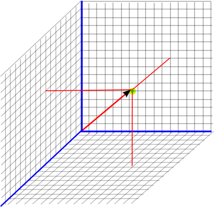
We can add a third dimension to our grid (to give x,y and z coordinates).
Left and Right Hand Coordinate Systems
The change to three dimensions gives us a new type of decision to make. It turns out that in three dimensions a coordinate system can be either 'left' or 'right' handed. However we rotate a left hand coordinate coordinate system we cant make it into a right hand coordinate system and visa-versa. One is the reflection of the other.
On this site we will standardise on a right hand coordinate system. (site standards)
- Any right hand coordinate system can be converted to any other right hand
coordinate system by rotating it.
- Any left hand coordinate system can be converted to any other left hand
coordinate system by rotating it.
- A right hand coordinate system cannot be converted to a left hand coordinate
system by rotating it.
Flipping any single axis will change a left hand axis to a right hand axis
or a right hand axis to a left hand axis, for example:
- Flipping positive X from right to left
- Flipping positive Y from up to down
- Flipping positive Z from toward to away.
So flipping any two axis will retain the same handedness.
Practical Issues
So how do we decide where to put the 'grid'? Often when we are working at a reasonable small scale so we can orient relative to the surface of the earth, 'up' being the direction of gravity field, we can also use the magnetic field 'north' to give another axis.
On a larger scale, there are various 'geospacial' coordinate systems as discussed on this page.
The standards used on this website are discussed here.
The standard used by this website, OpenGL and most 3D software is shown above.
However Engineering/CAD systems tend to use X,Y for the plan coordinates and
Z for up. (see message from Carl)
Each point in the world can be specified by 3 floating point numbers (float
or double), the X, Y and Z coordinates of that point.
These 3 numbers together(x,y,z) are known as a vector, and can specify any
point in 3D space. If the value of y is increased the point moves up, if it
is decreased the point moves down. If the value of x is increased the point
moves right, if it is decreased the point moves left. If the value of z is increased
the point moves toward the viewer, if it is decreased the point moves away.
A vector can also represent a relative movement in 3D, so for instance if you
start with the absolute position (0,2,-3) and add the vector (-1,4,6) we get
the position (-1,6,3) . Similarly we can subtract vectors.
There are 2 types of vector multiplication (dot and vector product) more details
when we cover normals and matrix topics).
3D vectors are supported by the java.vecmath package which is distributed with
java3D although it is a separate package. This supports a range of 2D, 3D and
4D points and vectors.
These have to be defined relative to some coordinate system.
Coordinate Systems in Computer Systems and Simulators
Local Coordinates
Coordinates relative to a node.
node.getLocalToVworld() - the composite of all the transforms from the root
to this node.
Virtual World coordinate systems
Defined by the locale object that contains the view platform
View Platform Coordinate systems
relative to the view platform.
|
root
.
.
trasformgroup
.
.
node |
tg.getBounds()
tg.getLocalToVWorld()
tg.getTransform() |
need to get bounds which are local to the node itself. To convert this
to virtual world coordinates need to transform it with getLocalToVWould()
and also getTransform() |
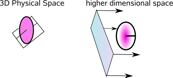
Higher Dimensions
Although the physical world we inhabit appears to have 3 dimensions of space and one of time, physics often postulates a world with a higher number of dimensions.
However, even if we are are modeling the three dimensional physical world, it is often useful to embed it in a higher dimensional just to make our calculations easier.
Examples of this are rotations, which are non-linear and difficult to manipulate when working in 3D physical space, we can work with rotations much easier if we embed them in a higher number of dimensions in such a way as the operations we want to do become linear. Examples of this are representing rotations by 3×3 matrices (9 dimensions) or quaternions (4 dimensions).
We can also use more complicated spaces which can handle movements of solid objects (isometries) in a linear way:
See also