Modeling collisions involves a lot of assumptions and approximations, also the concept of an 'impulse' is not always intuitively obvious. These issues are all discussed on the page above this and it may be worth reading that page before this.
One difficult bit is understanding how to work with objects that have both rotation and linear motion. The main method we will use to do this involves the following stages.
- Determine the collision point and the normal direction at this point.
- Calculate the minimum impulse to prevent the objects intersecting, or to
reverse the approach velocity, depending on the coefficient of friction.
- Calculate the effect of this impulse on the rotation and linear motion
separately.
The results, for this 3D case, are summarised as follows:
| |
General case |
| impulse
J = |
| -(1+e) |
(va-vb)•n + (ra×n)•ωa - (rb×n)•ωb |
 |
| 1/ma+1/mb+(ra×n)•([Ia]-1(ra×n))+(rb×n)•([Ib]-1(rb×n)) |
|
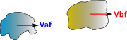
Final velocity of
object a=vaf
= |
vai - J/Ma |
Final velocity of
object b=vbf
= |
vbi + J/Mb |
| Final angular velocity of object a=waf
= |
wai - [Ia]-1(J × ra) |
| Final angular velocity of object b=wbf
= |
wbi + [Ib]-1(J × rb) |
Directions
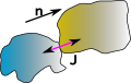
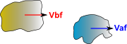
When we work out these equations manually its easy enough to work out the direction of the impulse and therefore the sign in the above terms but when this is part of a computer program its important to understand the conventions that we are assuming and to get the signs right.
In the following diagrams the arrows indicate the positive direction, not the absolute velocity, which may well be negative.
| before collision |
at collision |
after collision |
 |
 |
 |
| vai > vbi |
|
vaf <= vbf |
In this case vai > vbi before the collision and vaf <= vbf after. So the impulse subtracts momentum from object a and adds it to object b so we get:
vaf = vai - J/Ma
vbf =vbi + J/Mb
Now we reverse the order of object a and object b:
| before collision |
at collision |
after collision |
 |
 |
 |
| vbi > vai |
|
vbf <= vaf |
In this case vbi > vai before the collision and vbf <= vaf after. So the impulse subtracts momentum from object b and adds it to object a so we get:
vaf = vai + J/Ma
vbf =vbi - J/Mb
Now it seems a bit messy to get the program to test which is the highest velocity to decide which equations to use so its probably easier to use a negative J to indicate the second case. If you do this be aware that a negative J does not mean its pulling rather than compressing, it just means the objects have collided in the other direction.
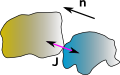
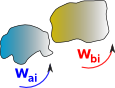
Rotation Directions
Things are more complicated with rotations in that angular momentum must be measured relative to some given point. So if object 'a' is rotating clockwise about its centre of mass it may well impart anticlockwise momentum to object 'b' about its own centre of mass. However this would not necessarily change the angular momentum of the total system, even for a closed system, due to the linear motion of the different centres of mass.
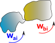
| before collision |
at collision |
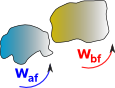
after collision |
 |
 |
 |
| ωbi >ωai |
|
ωbf <= ωaf |
velocity of collision point on object 'a' =
vpa = vca + ωa×(r-pa)
velocity of collision point on object 'b' =
vpb = vcb + ωb×(r-pb)
Derivation
As with the 1D case we can start with the definition of the coefficient of
restitution which is the ratio of converging and diverging velocities.
However, in this case, the velocities are not the velocities of the centre
of mass, they are the velocities of points (in absolute coordinates) on the
solid bodies, these are the points on the bodies that actually collide.
e = (vaf- vbf)
/ (vai - vbi)
| where: | |
symbol |
description |
type |
units |
| vcaf |
final velocity of collision
point on object a |
vector |
m/s |
| vcai |
initial velocity of collision
point on object a |
vector |
m/s |
| vcbf |
final velocity of collision
point on object b |
vector |
m/s |
| vcbi |
initial velocity of collision
point on object b |
vector |
m/s |
| e |
coefficient of restitution which depends on the nature of the two colliding
materials |
scalar |
none |
let Δvca = vcai - vcaf
This is the change in velocity of the collision point on body 'a' due to the
impulse.
and Δvcb = vcbi - vcbf
This is the change in velocity of the collision point on body 'b' due to the
impulse.
so,
e * (vcai - vcbi)=
-(vcaf- vcbf)
(e+1) * (vcai - vcbi)=
-(vcaf- vcbf)+(vcai
- vcbi)
(e+1) * (vcai - vcbi)=
Δvca + Δvcb
The way that Δvca
and Δvcb are
related to impulse (J) is explained on this
page, from that page we get:
ΔVp = J/M
+ ([I]-1(J × r)) × r
| where: | |
symbol |
description |
type |
units |
| Vp |
linear velocity of a particle on a solid body (vector) |
vector |
m/s |
| J |
impulse |
vector |
|
| I |
inertia scalar such that torque = I * alpha (only true when object is
symmetrical) |
scalar |
|
| [I] |
inertia tensor |
3×3 matrix |
|
| m |
mass |
scalar |
kg |
| • |
• = dot product |
|
|
| × |
× = cross product |
|
|
| r |
position of particle relative to centre of mass - Note: this
is in absolute coordinates, not local body coordinates, so this will be a
function of time as the body rotates. |
vector |
|
So we get:
(e+1) * (vai - vbi)=
J/Ma +([Ia]-1(J × ra)) x ra + J/Mb +([Ib]-1(J × rb)) x
rb
We want to solve this for J, to do this we need to separate out the J terms
on the right hand side. The direction of the impulse will depend on the nature
of the material colliding and its friction coefficient. If the friction is high
then the impulse will be in the direction of approach of the colliding points,
if the friction is low then the impulse will be perpendicular to the colliding
surfaces, there is no impulse parallel to the surface because they can slide
in that direction. So splitting the impulse into its magnitude and direction
can allow friction to be taken into account and allow the impulse magnitude
to be taken out of the right hand side as a common term.
J = n*|J|
| where: | |
symbol |
description |
type |
units |
| n |
normal vector which gives the direction of the impulse. |
vector |
|
| J |
impulse vector |
vector |
|
| |J| |
impulse magnitude |
scalar |
|
Assuming that there is such a solution we need to make
([Ia]-1(J × ra)) × ra = |J| * ([Ia]-1(n × ra)) × ra
So the result is:
|J| = (e+1) * (vai - vbi)
/ (1/Ma +n•([Ia]-1(n × ra)) x ra + 1/Mb +n•([Ib]-1(n
× rb)) × rb)
Code
/**
This function calulates the velocities after a 3D collision vaf, vbf, waf and wbf from information about the colliding bodies
@param double e coefficient of restitution which depends on the nature of the two colliding materials
@param double ma total mass of body a
@param double mb total mass of body b
@param matrix Ia inertia tensor for body a in absolute coordinates (if this is known in local body coordinates it must
be converted before this is called).
@param matrix Ib inertia tensor for body b in absolute coordinates (if this is known in local body coordinates it must
be converted before this is called).
@param vector ra position of collision point relative to centre of mass of body a in absolute coordinates (if this is
known in local body coordinates it must be converted before this is called).
@param vector rb position of collision point relative to centre of mass of body b in absolute coordinates (if this is
known in local body coordinates it must be converted before this is called).
@param vector n normal to collision point, the line along which the impulse acts.
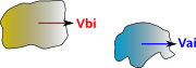
@param vector vai initial velocity of centre of mass on object a
@param vector vbi initial velocity of centre of mass on object b
@param vector wai initial angular velocity of object a
@param vector wbi initial angular velocity of object b
@param vector vaf final velocity of centre of mass on object a
@param vector vbf final velocity of centre of mass on object a
@param vector waf final angular velocity of object a
@param vector wbf final angular velocity of object b
*/
CollisionResponce(double e,double ma,double mb,matrix Ia,matrix Ib,vector ra,vector rb,vector n,
vector vai, vector vbi, vector wai, vector wbi, vector vaf, vector vbf, vector waf, vector wbf) {
matrix IaInverse = Ia.inverse();
vector normal = n.normalise();
vector angularVelChangea = normal.copy(); // start calculating the change in abgular rotation of a
angularVelChangea.cross(ra);
IaInverse.transform(angularVelChangea);
vector vaLinDueToR = angularVelChangea.copy().cross(ra); // calculate the linear velocity of collision point on a due to rotation of a
double scalar = 1/ma + vaLinDueToR.dot(normal);
matrix IbInverse = Ib.inverse();
vector angularVelChangeb = normal.copy(); // start calculating the change in abgular rotation of b
angularVelChangeb.cross(rb);
IbInverse.transform(angularVelChangeb);
vector vbLinDueToR = angularVelChangeb.copy().cross(rb); // calculate the linear velocity of collision point on b due to rotation of b
scalar += 1/mb + vbLinDueToR.dot(normal);
double Jmod = (e+1)*(vai-vbi).magnitude()/scalar;
vector J = normal.mul(Jmod);
vaf = vai - J.mul(1/ma);
vbf = vbi - J.mul(1/mb);
waf = wai - angularVelChangea;
wbf = wbi - angularVelChangeb;
}
Alternative method using matrices
It seems like a good idea to express all terms using the same type of algebra,
it is not possible to express inertia tensor purely in terms of vectors or quaternions
so can we calculate purely in terms of matrices?
The relationship between impulse J and the change in velocity of the point
where J is applied is derived here
giving:
|
Change in linear velocity of a point on a solid body due to J=
J/M + ([I]-1(J × r)) × r |
| -ixx*rz*rz + ixz*rx*rz -ixx*ry*ry
+ ixy*rx*ry + 1/M |
-ixy*rz*rz + ixz*ry*rz +ixx*ry*rx
- ixy*rx*rx |
ixy*rz*ry - ixz*ry*ry + ixx*rz*rx
- ixz*rx*rx |
| -iyx*rz*rz + iyz*rx*rz -iyx*ry*ry - iyy*rx*ry |
-iyy*rz*rz + iyz*ry*rz + iyx*ry*rx - iyy*rx*rx
+ 1/M |
iyy*rz*ry - iyz*ry*ry + iyx*rz*rx - iyz*rx*rx |
| -izx*rz*rz + izz*rx*rz -izx*ry*ry
+ izy*rx*ry |
-izy*rz*rz + izz*ry*rz + izx*ry*rx
+ izy*rx*rx |
izy*rz*ry - izz*ry*ry
+ izx*rz*rx - izz*rx*rx + 1/M |
|
|
Where;
| where: | other definitions |
symbol |
description |
type |
units |
| ixx to izz |
elements of inverse inertia tensor (in absolute coordinates) |
|
|
| rx,ry and rz |
point at which impulse is applied relative to centre of mass
(in absolute coordinates) |
|
|
So we now include the effect of J on the relative velocities of bodies A and
B:
|
Change in relative linear velocity of collision point due to J=
(e+1) * (vai - vbi)= |
| -iaxx*raz*raz + iaxz*rax*raz -iaxx*ray*ray
+ iaxy*rax*ray + 1/Ma -ibxx*rbz*rbz + ibxz*rbx*rbz
-ibxx*rby*rby + ibxy*rbx*rby + 1/Mb |
-iaxy*raz*raz + iaxz*ray*raz +iaxx*ray*rax
- iaxy*rax*rax -ibxy*rbz*rbz + ibxz*rby*rbz
+ibxx*rby*rbx - ibxy*rbx*rbx |
iaxy*raz*ray - iaxz*ray*ray +
iaxx*raz*rax - iaxz*rax*rax + ibxy*rbz*rby
- ibxz*rby*rby + ibxx*rbz*rbx - ibxz*rbx*rbx |
| -iayx*raz*raz + iayz*rax*raz -iayx*ray*ray - iayy*rax*ray
-ibyx*rbz*rbz + ibyz*rbx*rbz -ibyx*rby*rby - ibyy*rbx*rby |
-iayy*raz*raz + iayz*ray*raz + iayx*ray*rax
- iayy*rax*rax + 1/Ma - ibyy*rbz*rbz + ibyz*rby*rbz + ibyx*rby*rbx
- ibyy*rbx*rbx + 1/Mb |
iayy*raz*ray - iayz*ray*ray + iayx*raz*rax
- iayz*rax*rax + ibyy*rbz*rby - ibyz*rby*rby + ibyx*rbz*rbx
- ibyz*rbx*rbx |
| -iazx*raz*raz + iazz*rax*raz -iazx*ray*ray
+ iazy*rax*ray -ibzx*rbz*rbz + ibzz*rbx*rbz
-ibzx*rby*rby + ibzy*rbx*rby |
-iazy*raz*raz + iazz*ray*raz +
iazx*ray*rax + iazy*rax*rax
-ibzy*rbz*rbz + ibzz*rby*rbz + ibzx*rby*rbx
+ ibzy*rbx*rbx |
iazy*raz*ray - iazz*ray*ray
+ iazx*raz*rax - iazz*rax*rax + 1/Ma + ibzy*rbz*rby
- ibzz*rby*rby + ibzx*rbz*rbx - ibzz*rbx*rbx
+ 1/Mb |
|
|
Therefore we need to invert this matrix to get an expression for J in terms
of the approch velocity, can anyone help me with this?
Other Methods
Solution using impulse
impulse transferred between objects= [NEMa]* (vaf
- vai)= -[NEMb]*(vbf
- vbi)
where:
- [NEMa] = Newton-Euler Matrix
 for object a , this is a 6x6 element matrix.
- [NEMb] = Newton-Euler Matrix for object b, this is a 6x6 element matrix.
- vaf= final velocity for object
a, this is a vector of dimension 6 containing both the linear and rotational
components in all 3 dimensions. (see
here for explanation)
- vai= initial velocity for object
a, this is a vector of dimension 6 containing both the linear and rotational
components in all 3 dimensions.
- vbf= final velocity for object
b, this is a vector of dimension 6 containing both the linear and rotational
components in all 3 dimensions.
- vbi= Initial velocity for object
b, this is a vector of dimension 6 containing both the linear and rotational
components in all 3 dimensions.
Note: I am assuming that in the elastic case, that only the linear part of
the impulse is transferred between the objects. The external torque is therefore
always zero, so the above equation holds true. In the inelastic case there may
be an rotational impulse transferred?
The only situation that I can think of where an elastic rotational impulse
might occur is the collision of two rotating masses on the same screw thread.
Can anyone help me clarify this? Do we need to consider rotational impulse component
in the collision of free floating solid objects?
perfectly inelastic collision
First take the case of perfectly inelastic collisions (where the objects stick
together after collision) and their final velocity is equal.
So,
vaf = vbf
(this is not quite true because when the objects stick together they will start
orbiting around each other, but they will have the same average velocity, which
is the velocity of the common centre of mass)
[NEMa]* (vaf - vai)=
-[NEMb]*(vbf - vbi)
so substitutingvaf for vbf
gives:
[NEMa]* (vaf - vai)=
[NEMb]*(-vaf+vbi)
we want to solve to find the value for vaf,
when multiplying matrix an vector, multiplication is distributive over addition
so,
[NEMa]* vaf - [NEMa]*vai=[NEMb]*vbi-
[NEMb]*vaf
We can rearrange these vectors to give:
[NEMa]* vaf + [NEMb]*vaf
= [NEMb]*vbi + [NEMa]*vai
I don't know enough about matrix algebra to proceed further here so I'll expand
out the terms:
| iaxx |
iaxy |
iaxz |
0 |
-haz |
hay |
| iayx |
iayy |
iayz |
haz |
0 |
-hax |
| iazx |
iazy |
iazz |
-hay |
hax |
0 |
| 0 |
haz |
-hay |
ma |
0 |
0 |
| -haz |
0 |
hax |
0 |
ma |
0 |
| hay |
-hax |
0 |
0 |
0 |
ma |
|
| waxf |
| wayf |
| wazf |
| vaxf |
| vayf |
| vazf |
|
+ |
| ibxx |
ibxy |
ibxz |
0 |
-hbz |
hby |
| ibyx |
ibyy |
ibyz |
hbz |
0 |
-hbx |
| ibzx |
ibzy |
ibzz |
-hby |
hbx |
0 |
| 0 |
hbz |
-hby |
mb |
0 |
0 |
| -hbz |
0 |
hbx |
0 |
mb |
0 |
| hby |
-hbx |
0 |
0 |
0 |
mb |
|
| waxf |
| wayf |
| wazf |
| vaxf |
| vayf |
| vazf |
|
= |
| iaxx |
iaxy |
iaxz |
0 |
-haz |
hay |
| iayx |
iayy |
iayz |
haz |
0 |
-hax |
| iazx |
iazy |
iazz |
-hay |
hax |
0 |
| 0 |
haz |
-hay |
ma |
0 |
0 |
| -haz |
0 |
hax |
0 |
ma |
0 |
| hay |
-hax |
0 |
0 |
0 |
ma |
|
| waxi |
| wayi |
| wazi |
| vaxi |
| vayi |
| vazi |
|
+ |
| ibxx |
ibxy |
ibxz |
0 |
-hbz |
hby |
| ibyx |
ibyy |
ibyz |
hbz |
0 |
-hbx |
| ibzx |
ibzy |
ibzz |
-hby |
hx |
0 |
| 0 |
hbz |
-hby |
mb |
0 |
0 |
| -hbz |
0 |
hbx |
0 |
mb |
0 |
| hby |
-hbx |
0 |
0 |
0 |
mb |
|
| wbxi |
| wbyi |
| wbzi |
| vbxi |
| vbyi |
| vbzi |
|
Hmmm I'm not sure that helps! But perhaps there is a way forward, perhaps we
could replace the two matrices on the left of the equation with a single matrix
which represents the inertia/mass of the combined objects. This also gets round
the earlier problem that the two objects orbit round each other, so have a different
combined inertia/mass matrix anyway. So,
[NEMcombined]* vaf = [NEMb]*vbi
+ [NEMa]*vai
so the solution is:
vaf = vbf
=[NEMcombined]inverse * ( [NEMb]*vbi
+ [NEMa]*vai )
The value of the impulse is:
impulse = [NEMa]* (vaf - vai)
impulse = [NEMa]* ([NEMcombined]inverse* ( [NEMb]*vbi
+ [NEMa]*vai ) - vai)
perfectly elastic collision
In this case assume that the equation for impulse is the same as inelastic
case (but its value is twice because the objects separate at the same rate that
they approach).
I don't think this is strictly the case as, in the 3D case without friction
then the impulse should be normal to the collision surface, and the rotational
impulse should be zero. Can anyone suggest how to calculate the value of this
impulse?
impulse = 2 [NEMa]* ([NEMcombined]inverse * ( [NEMb]*vbi
+ [NEMa]*vai ) - vai)
Final velocity = initial velocity + impulse
vaf = vai
+ 2 [NEMa]* ([NEMcombined]inverse * ( [NEMb]*vbi
+ [NEMa]*vai ) - vai)
Solution using consevation of momentum and energy
By conservation of linear momentum:
 * [
* [ ,
, ,
, ]
+
]
+  * [
* [ ,
, ,
, ]
= * [
]
= * [ ,
, ,
, ]
+ * [
]
+ * [ ,
, ,
, ]
]
By conservation of angular momentum:
where all the rotations in the above equation are about the same point, as
explained in the 2D case. If we want to measure the rotations about the objects
own centre of mass, then we need to apply the parallel axis theorem, which will
add another term to the above equation.
By conservation of energy
 *
+
*
+  *
+
*
+  *
+ Ixx sqr wx + Iyy sqr wy + Izz sqr wz - 2Ixy wx wy - 2Ixz wx wz - 2Iyz wy wz
+
*
+ Ixx sqr wx + Iyy sqr wy + Izz sqr wz - 2Ixy wx wy - 2Ixz wx wz - 2Iyz wy wz
+
 *
+
*
+  * +
* +
 *
+ Ixx sqr wx + Iyy sqr wy + Izz sqr wz - 2Ixy wx wy - 2Ixz wx wz - 2Iyz wy wz
=
*
+ Ixx sqr wx + Iyy sqr wy + Izz sqr wz - 2Ixy wx wy - 2Ixz wx wz - 2Iyz wy wz
=
 *
+
*
+  * +
* +
 *
+ Ixx sqr wx + Iyy sqr wy + Izz sqr wz - 2Ixy wx wy - 2Ixz wx wz - 2Iyz wy wz
+
*
+ Ixx sqr wx + Iyy sqr wy + Izz sqr wz - 2Ixy wx wy - 2Ixz wx wz - 2Iyz wy wz
+
 *
+
*
+  * +
* +
 *
+ Ixx sqr wx + Iyy sqr wy + Izz sqr wz - 2Ixy wx wy - 2Ixz wx wz - 2Iyz wy wz
*
+ Ixx sqr wx + Iyy sqr wy + Izz sqr wz - 2Ixy wx wy - 2Ixz wx wz - 2Iyz wy wz
This gives 7 equations with 12 unknowns so we need extra in formation to solve
them:
- velocity of a : ,
and
- velocity of b : ,
and
- rotation of a about x axis: wax
- rotation of a about y axis: way
- rotation of a about z axis: waz
- rotation of b about x axis: wbx
- rotation of b about y axis: wby
- rotation of b about z axis: wbz
So there is insufficient information here to solve these equations so we need
to add additional information, such as any constraints that apply, or apply
'angle of incidence = angle of reflection'.
Even if we have enough information to solve in a general case the equations
are very complicated to solve for the general case. Specially since we are not
usually working in the frame-of-reference of the individual shapes, so in general
the I(Inertia) terms will be a function of the angles of the object as it rotates,
this will make the equations very complicated. So we may need to take a different
approach, as follows:
Assume we move to the frame of reference of shape 1, therefore shape 1 will
always appear stationary in this frame. The movement of shape 2 will be easier
to calculate in this frame, for example, if we assume that the impulse is in
the direction of the normal only (no sliding). Therefore its motion parallel
to the plane will be constant and its motion normal to the plane will be reversed
during the collision. There may be energy transferred between the linear and
angular motion, depending on the relative positions of the centre-of-mass of
shape 2 and the point of collision, but as a first approximation it may be possible
to ignore that?
We still have to calculate how the movement of the frame-of-reference has changed
in the collision, but this should be relatively easy using the conservation
of momentum.
So how to move to the frame-of-reference of shape 1? All we have to do is move
shape 2 under shape 1 in the scene graph, not forgetting to translate all the
parameters associated with the shape.
So the transform [T8] gives the position of shape 2 relative to shape 1.
where in this case:
[T8] = [T7][T3][inverse T2][inverse T5]
We must not forget to transform all the kinematics and dynamics parameters
for shape 2 also.
Rotation Component for 3d example above
If we assume that both objects are traveling in free space (no external torque),
then they collide, then they travel again in free space.
As described above, the initial rotations are known, and we want to determine
the final rotations. At the collision, energy may be transferred between the
colliding objects, and between linear and rotational energies.
The conservation laws of momentum and energy above are not enough to determine
the final velocities. We need to take into account other factors determined
by the geometry of the objects.
One factor is that the objects can only rotate about certain axes (see
no torque). If the object is a perfect sphere (or at least its inertia terms
are equal in all directions). Then the object can rotate in any direction, but
at least we can use its symmetry to simplify the equations. If the objects are
not symmetrical, then they can only rotate about certain axes which will limit
the possible outcomes.
Another factor is the position of the point of impact, relative to the centre
of masses of the two objects.
If this is too complicated then you might want to consider a numerical
approach to collisions.
This site may have errors. Don't use for critical systems.
