Allows us to create structures representing morphisms between objects.
At the simplest level hom-set allows us to create a named set of objects together with a set of arrows between them.
We can then go on to create higher order objects such as natural transformations (arrows between arrows) and so on upto any level.
The way that we model hom-set is designed to scale up to very large models therefore the model is mutable so that we can add things to it in an efficient way.
Hom-Set Model Representation
The model consists of 3 tables:
Nodes Table
This table has an entry for each object
| Name (String) | X coord (NNI) | Y coord (NNI) |
|---|---|---|
Entries in this table are indexed by the following tables so the order of the objects can't be changed unless the index numbers in the following tables are changed.
Arrows Table
This has two levels of table, the first inner table contains a list of arrows between objects, the next inner table contains a list of arrows between arrows, and so on.
| Level | Inner Table | ||||||||||||
|---|---|---|---|---|---|---|---|---|---|---|---|---|---|
| Arrows: | this is the first inner table and the index values are indexes to the object table above.
|
||||||||||||
| Natural Transformation: | this is the next inner table and the index values are indexes to the arrow table above. For a Natural Transformation to be valid then, both the from-index and to-index must be mapped to arrows between the same objects, this may not be enforced by the software.
|
||||||||||||
| Next level and so on: | following inner tables index into the table above it.
|
In the above tables 'arrType' has the following values:
- Equality
- Isomorphism
- Equivalence
- Adjunction
Commutes Table
This table indicates which arrows commute. It takes entries from the Record(level:NNI,index:NNI) and forms them into a list which represents arrow (function) composition.
| First Composition | Second Composition | |||||||||||||||||||
|---|---|---|---|---|---|---|---|---|---|---|---|---|---|---|---|---|---|---|---|---|
This table represents a sequence of arrows where the target of the first arrow must be the source of the next arrow and so on.
|
|
|||||||||||||||||||
|
|
The result of the first composition must be the same as the second composition, that is they must commute.
So each entry in the outer table represents a requirement that somthing must commute.
Representation
This is coded as follows:
Rep := Record(_
   objects: List OBJT,_
   arrows:List List ARROW,_
   commutes:List COMM_
   )
Where:
 OBJT ==> Record(name:String,posX:NNI,posY:NNI)
 ARROW ==> Record(name:String,arrType:NNI,fromOb:NNI,toOb:NNI)
 COMM ==>Record(List Record(NNI,NNI),List Record(NNI,NNI))
Hom-Set Tutorial
The hom-set domain needs to be installed on your system. The source code is in a file called homset.spad.pamphlet, which is available here: https://github.com/martinbaker/multivector/ Download and compile in the usual way. Make sure it is exposed since Axiom/FriCAS was started.
(1) -> )library HOMSET

   HomSet is now explicitly exposed in frame frame1
   HomSet will be automatically loaded when needed from
/home/martin/HOMSET.NRLIB/HOMSET |
First we will create a very simple hom-set without any information for creating diagrams.
We begin by creating a set of objects, each of which is identified by its name, in this case "a" and "b".
(1) -> hs := homSet(["a","b"])

   (1)  "a,b"
Type: HomSet |
At any time we can add more objects with the addObject! function:
(2) -> addObject!(hs,"c")

   (2)  "a,b,c"
Type: HomSet |
Now we have some objects to play with we can add arrows between them by using the addArrow! function. This identifies the source and target of each arrow by its index into the list of objects.
(3) -> addArrow!(hs,"alpha",1,2)

   (3)  "a,b,c|alpha:a->b"
Type: HomSet |
We could go on to add more objects and arrows but hopefully this is enough to explain the principles.
We will now start a new hom-set model which is suitable for creating diagrams. For diagrams the objects not only need a name (string) but they also need a position in a two dimentional plane. The x and y coordinates are represented by integers in a 100 by 100 square.
This information about each object is representd by a structure which we will define:
(4) -> OBJT ==> Record(name:String,posX:NNI,posY:NNI)
Type: Void |
We will create 3 instances of this structure to represent the objects oba, obb and obc each with different positions:
(5) -> oba:OBJT := ["a",10,10] (5) [name= "a",posX= 10,posY= 10] Type: Record(name: String,posX: NonNegativeInteger,posY: NonNegativeInteger) (6) -> obb:OBJT := ["b",10,60] (6) [name= "b",posX= 10,posY= 60] Type: Record(name: String,posX: NonNegativeInteger,posY: NonNegativeInteger) (7) -> obc:OBJT := ["c",60,10] (7) [name= "c",posX= 60,posY= 10] Type: Record(name: String,posX: NonNegativeInteger,posY: NonNegativeInteger) |
We can now put these objects into a new model:
(8) -> hs2 := homSet([oba,obb,obc])

   (8)  "a,b,c"
Type: HomSet |
and we can create some arrows between the objects as we did with the previous model:
(9) -> addArrow!(hs2,"alpha",1,2)

   (9)  "a,b,c|alpha:a->b"
                                                             Type: HomSet

(10) -> addArrow!(hs2,"beta",2,3)

   (10)  "a,b,c|alpha:a->b,beta:b->c"
Type: HomSet |
Now we can output to an SVG diagram
(11) -> diagramSvg("tesths.svg",hs2)

Type: Void |
| This diagram needs to be tweeked by hand, using a program such as Inkscape, to look better. | 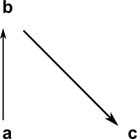 |
We will now create another model to show how we can model structures such as natural transformations. using arrows between arrows. We begin by constructing two objects G and H which we put into a model:
(12) -> obg:OBJT := ["G",10,50]

   (12)  [name= "G",posX= 10,posY= 50]
 Type: Record(name: String,posX: NonNegativeInteger,posY: NonNegativeInteger)
(13) -> obh:OBJT := ["H",60,50]

   (13)  [name= "H",posX= 60,posY= 50]
 Type: Record(name: String,posX: NonNegativeInteger,posY: NonNegativeInteger)
(14) -> hs2 := homSet([obg,obh])

   (14)  "G,H"
Type: HomSet |
We can then add two arrows from G to H, this uses the extended form of the addArrow! function which allows us to supply the following parameters:
- s = model to oerate on
- level:NNI: 1=obj->obj, 2=arrow->arrow, and so on.
- nm:String: name of this arrow
- n1:NNI: from index
- n2:NNI: to index
- x:Integer: x coordinate offset
- y:Integer: y coordinate offset
The following two arrows both go from G to H so they are level 1. In order that these two arrows are not superimposed we set 'a1' to have a y coodinate offet of +10 and 'a1' to have a y coodinate offet of -10
(15) -> addArrow!(hs2,1,"a1",1,2,0,10)

   (15)  "G,H|a1:G->H"
                                                             Type: HomSet
(16) -> addArrow!(hs2,1,"a2",1,2,0,-10)

   (16)  "G,H|a1:G->H,a2:G->H"
Type: HomSet |
We can now add and arrow at level 2, that is an arrow from an arrow to another arrow:
(17) -> addArrow!(hs2,2,"b1",1,2,0,0)

   (17)  "G,H|a1:G->H,a2:G->H|b1:a1=>a2"
Type: HomSet |
We can now draw a diagram for this model:
(18) -> diagramSvg("tesths2.svg",hs2)

Type: Void |
| This diagram needs to be tweeked by hand, using a program such as Inkscape, to look better. | 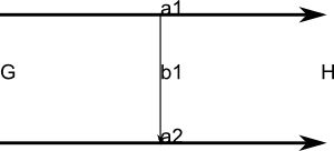 |