Equations
We can express the 3×3 rotation matrix in terms of a 3×3 matrix representing the axis (The 'tilde' matrix is explained here):
[R] = [I] + s*[~axis] + t*[~axis]2
or equivalently:
[R] = c*[I] + s*[~axis] + t*([~axis]2 + [I])
which can be expanded out to give the terms of the matrix components:
| [R] = |
|
where,
- c =cos(angle)
- s = sin(angle)
- t =1 - c
- x = normalised axis x coordinate
- y = normalised axis y coordinate
- z = normalised axis z coordinate
This can be written as the sum of 3 matricies:
- The identity matrix times c.
- A matrix which is symmetrical about the leading diagonal.
- A matrix which is antisymmetrical about the leading diagonal (term on other side of diagonal is negative).
|
= c* |
|
+ t* |
|
+s* |
|
Code
 public void matrixFromAxisAngle(AxisAngle4d a1) {

    double c = Math.cos(a1.angle);
    double s = Math.sin(a1.angle);
    double t = 1.0 - c;
	//  if axis is not already normalised then uncomment this
	// double magnitude = Math.sqrt(a1.x*a1.x + a1.y*a1.y + a1.z*a1.z);
	// if (magnitude==0) throw error;
	// a1.x /= magnitude;
	// a1.y /= magnitude;
	// a1.z /= magnitude;

    m00 = c + a1.x*a1.x*t;
    m11 = c + a1.y*a1.y*t;
    m22 = c + a1.z*a1.z*t;


    double tmp1 = a1.x*a1.y*t;
    double tmp2 = a1.z*s;
    m10 = tmp1 + tmp2;
    m01 = tmp1 - tmp2;
    tmp1 = a1.x*a1.z*t;
    tmp2 = a1.y*s;
    m20 = tmp1 - tmp2;
    m02 = tmp1 + tmp2;    tmp1 = a1.y*a1.z*t;
    tmp2 = a1.x*s;
    m21 = tmp1 + tmp2;
    m12 = tmp1 - tmp2;
}
Derivation of Equations

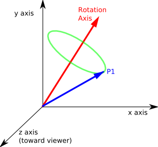
Imagine we want to rotate a point P1 (denoted in the above diagram by the blue vector). The axis we want to rotate around is denoted by the red vector.
The track of the point as it rotates will form a circle (shown in green) in a given plane.
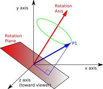
In the diagram below this plane has been moved down so that it passes through the origin. This plane is defined by the rotation axis (the plane is perpendicular to the axis).

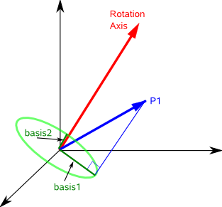
We now want to generate two basis vectors in the plane which we can use to define the circle in our global coordinate system. To get one of these basis vectors we can cross multiply axis with P1, this gives a vector in the plane at 90° to the projection of P1 onto the plane. For information about vector algebra and cross products see this page.
basis2 = axis × P1
where:
- basis2 = second basis vector
- axis = direction of rotation as a normalised (unit length) vector
- × = vector cross product.
- P1 = point being rotated.
The first basis vector is just the projection of the vector P1 onto the plane (Projection of a line onto a plane is explained on this page).
This will be a vector mutually perpendicular to axis and basis2, so,
basis1 = basis2 × axis
basis1 = (axis × P1) × axis
These basis vectors are shown on the following diagram:

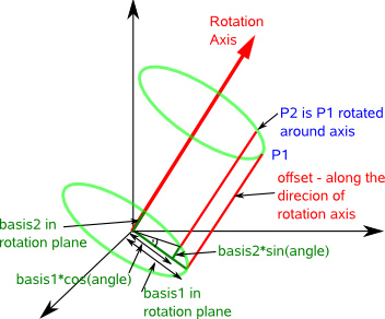
Therefore the track of the circle is given by a linear product of these vectors as follows:
cos(angle) * basis1 + sin(angle) * basis2
actually this is not quite the circle required as the circle has been offset to the origin therefore we need to move it back therefore:
P2 = offset + cos(angle) * basis1 + sin(angle) * basis2
where:
- P2 = transform of point P1
- offset = distance of centre of circle from origin
- angle = angle that we are rotating around the axis

From the diagram we can see that:
offset = P1 - basis1
Therefore substituting this values gives:
P2 = P1 - basis1 + cos(angle) * basis1 + sin(angle) * basis2
P2 = P1 + (cos(angle) - 1) * basis1 + sin(angle) * basis2
substituting the basis values above gives:
P2 = P1 + (cos(angle) - 1) * ((axis × P1)×axis) + sin(angle)*(axis × P1)
However this uses vector algebra, we need to convert this into matrix algebra, we can do this by using the skew symmetric or 'tilde' matrix as described on this page.
if V = A × B
then V = [~A]B
where:
| [~A] = |
|
So converting to matrix form gives:
P2 = P1 + (cos(angle) -1)*([~axis]P1 × axis) + sin(angle)*[~axis]P1
There is still one vector cross product here, to remove it we will first change the order by using the anticommute law:
P2 = P1 + (1 - cos(angle))*(axis× [~axis]P1) + sin(angle)*[~axis]P1
Now we can substitute the skew symmetric [~axis] as before:
P2 = P1 + (1 - cos(angle))*([~axis]²P1) + sin(angle)*[~axis]P1
gathering the P1 terms together gives:
P2 = [I + (1 - cos(angle))[~axis]2 + sin(angle)[~axis]] P1
Let the rotation matrix be [R] where:
P2 = [R] P1
so the rotation matrix is
[R] = [I] + sin(angle)[~axis] + (1-cos(angle))[~axis]2
where:
- [R] = rotation matrix we want to derive
- [I] = identity matrix
- axis = axis vector (x,y,z) normalised to unit length
- [~axis] = 'tilde' matrix
For information about the derivation of this see message from Sven.
| [I] = |
|
| [~axis] = |
|
| [~axis]2 = |
|
since x*x + y*y + z*z = 1 then,
| [~axis]2 = |
|
therefore:


