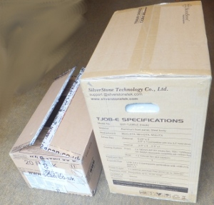
This page follows on from the previous steps here.
I thought it best, at this stage to do a quick test of the components installed so far. That is do a test while the motherboard is not yet installed in the case then, if there were a problem, we could investigate without needing to take out any wiring.
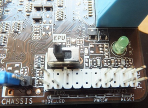
First a check to make sure all mechanical switches are in the correct position:
The EPU switch allows the UEFI/BIOS to detect the PC loadings and moderate the power consumption. It is already to the left which enables the EPU boost, so I left it on that setting. |
 |
| This switch was also left on the default setting which enables the GPU boost. | 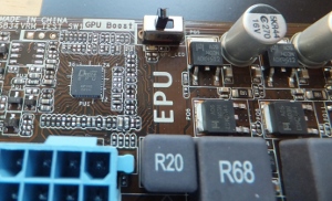 |
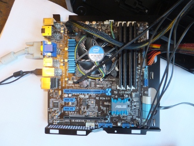
Now temporarily wire the motherboard to the power supply and other components:
| Its a bit of a mess but its good enough for a temporary test rig. | 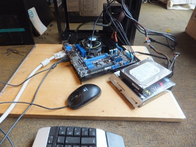 |
I connected to the motherboard::
Also external components:
|
 |
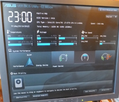
When first switched on, the screen was blank for a long time, then this appeared.
Its a relief that, at least the basic functionality appears to be there.
On the following page we go on to install everything properly in the case.