As a command, XID solicits the identification of the receiving (secondary) station. An information field may be included in the frame to convey identification of the transmitting (primary) station. An XID response is required from the secondary station. An information field in the response may be used for identification of the responding secondary station.
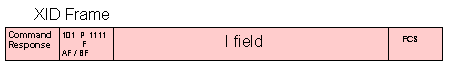
XID Information Field Format
| Byte | Bit | Value | Meaning |
| 0 | 0-3 | 0 | fixed format: only bytes 0-5 are included |
| 1 | variable format: bytes 0-p are included | ||
| 2 | " | ||
| 3 | " | ||
| 8-F | defined for external standards organisations | ||
| 4-7 | 1 | type of the XID-sending node: T1 | |
| 2 | T2 | ||
| 3 | reserved | ||
| 4 | subarea node T4/T5 | ||
| 1 | p | length in binary of variable-format XID I-field | |
| 2-5 | 0-11 | block number: an IBM product specific number | |
| 12-31 | ID number: a binary value that, together with | ||
| the block number, identifies a specific station | |||
| uniquely within a customer network installation | |||
| ID Information Field Format - continuation for format 1 | |||
| 6-7 | reserved | ||
| 8 | 0 | reserved | |
| 2 | 0 | sender is a secondary link station -nonnegotiable | |
| 1 | sender is a primary link station -nonnegotiable | ||
| 3 | reserved | ||
| 4-7 | 0 | two-way alternating | |
| 1 | two-way simultaneous | ||
| 9 | 0-1 | reserved | |
| 2-3 | segment assembly capability of the path control | ||
| element of the node: | |||
| 00 | the mapping field is ignored and PIUs are | ||
| forwarded unchanged | |||
| 01 | segments are assembled on a link-station basis | ||
| 10 | segments are assembled on a session basis | ||
| 11 | only whole BIUs are allowed | ||
| 4-5 | reserved | ||
| 6 | short-hold status | ||
| 0 | sender not already engaged in a logical | ||
| connection using short-hold mode. | |||
| 1 | sender already engaged in a logical connection | ||
| using short-hold mode. | |||
| 7 | 0 | short hold mode not supported | |
| 1 | short hold mode supported |
XID Information Field Format - continuation for format 1
| Byte | Bit | Value | Meaning |
| 10-11 | 0 | 0 | bits 1-15 contain the maximum I-field length |
| 1-15 | maximum I-field length in binary | ||
| 12 | 0-3 | reserved | |
| 4-7 | 0 | SNA link profile eg: | |
| link in NRM | |||
| supporting the following: | |||
| COMMANDS RESPONSES | |||
| I-frames I-frames | |||
| RR RR | |||
| RNR RNR | |||
| TEST TEST | |||
| XID XID | |||
| SNRM UA | |||
| DISC DM | |||
| RD | |||
| FRMR | |||
| REJ REJ | |||
| 13 | 0-1 | reserved | |
| 2 | 0 | SIM and RIM not supported | |
| 1 | SIM and RIM supported | ||
| 3-7 | reserved | ||
| 14-15 | reserved | ||
| 16 | 0 | reserved | |
| 1-7 | max number of I-frames that can be received by | ||
| the XID sender before an ack is sent | |||
| 0-7 | mod 8 | ||
| 8-127 | mod 128 | ||
| 17 | reserved | ||
| 18-p | SDLC address assignment field | ||
| or Short hold mode dependant parameters | |||
| or dial digits of XID sender |
XID InformationField Format - continuation for format 2
| Byte | Bit | Value | Meaning |
| 6-7 | reserved | ||
| 8 | 0 | 0 | TG inactive |
| 1 | TG active | ||
| 1 | 0 | multiple link TG not supported | |
| 1 | multiple-link TG supported | ||
| 2-3 | 00 | segments are ignored and passed through | |
| 01 | segments are assembled on a link station basis | ||
| 10 | segments are assembled on a session basis | ||
| 11 | segments are not allowed | ||
| 4-7 | reserved | ||
| 9 | 0 | 0 | FID 0 not supported |
| 1 | FID 0 supported | ||
| 1 | 0 | FID 1 not supported | |
| 1 | FID 1 supported | ||
| 2-3 | reserved | ||
| 4 | 0 | FID 4 not supported | |
| 1 | FID 4 supported | ||
| 5-7 | reserved | ||
| 10 | reserved | ||
| ID Information Field Format - continuation for format 2 | |||
| Byte | Bit | Value | Meaning |
| 11-12 | length in binary of max PIU that the XID sender | ||
| can receive | |||
| 13 | transmission group number TGN | ||
| 14-17 | subarea address of the XID sender | ||
| 18 | 0 | reserved | |
| 1-4 | 0 | error status: no error | |
| 8 | exchanged parameters in the XIDs are not compatib | ||
| 9 | incompatible parameters (max PIU length) | ||
| A | TG is not defined (no routing found) | ||
| C | the specified TG between the subarea nodes | ||
| exchanging XIDs is already active | |||
| 5-7 | reserved | ||
| 19 | CONTACT or load status of XID sender: | ||
| 0 | CONTACT has been received by an XID sender | ||
| 7 | XID response sender is already loaded | ||
| 20-27 | IPL load module name: an 8-character EBCDIC | ||
| symbolic name of the IPL load module of the | |||
| XID sender X'40 ... 40'= no information | |||
| 28-29 | Reserved | ||
| 30 | 01 | DLC type: SDLC | |
| 02 | system/370 channel | ||
| 03 | system/370 to system/370 channel | ||
| 31-n | DLC dependant parameters |
XID Information Field Format - continuation for format 3
| Byte | Bit | Value | Meaning |
| 6-7 | reserved | ||
| 8-9 | 0 | 0 | Init-self may be sent to the XID sender |
| 1 | Init-self cannot be sent to the XID sender | ||
| 1 | 0 | BIND may be sent to the XID sender without a | |
| prior Init-self | |||
| 1 | Bind may not be sent ... | ||
| 2-3 | segment assembly capability of path control | ||
| 00 | mapping field is ignored | ||
| 01 | reserved | ||
| 10 | segments are assembled on a session basis | ||
| 11 | only whole BIUs are allowed | ||
| 4-7 | FID types that the node supports | ||
| 0000 | FID type 2 (only value defined) | ||
| 8 | dependant CNM services | ||
| 0 | maintenance services required | ||
| 1 | maintenance services not required | ||
| 9-15 | reserved | ||
| 10-16 | reserved | ||
| 17 | X'01' | DLC type: SDLC Normal response mode (only val def) | |
| 18 | length in binary of DLC dependant section | ||
| 19 | link station and connection protocol flags | ||
| 0-1 | reserved | ||
| 2-3 | link station role of XID sender | ||
| 00 | sender is a secondary link station | ||
| 01 | sender is a primary link station | ||
| 10 | reserved | ||
| 11 | negotiable (primary or secondary) | ||
| 4-5 | reserved | ||
| 6-7 | link-station transmit-receive capability | ||
| 00 | two-way alternating | ||
| 01 | two-way simultaneous | ||
| 20 | reserved | ||
| 21-22 | maximum I-field length that the XID sender can | ||
| receive: | |||
| 0 | 0 | bits 1-15 contain max I-field length | |
| 1-15 | max I-field length, in binary |
XID Information Field Format - continuation for format 3
| Byte | Bit | Value | Meaning |
| 23 | 0-3 | reserved | |
| 4-7 | 0 | SNA link profile eg: | |
| link in NRM | |||
| supporting the following: | |||
| COMMANDS RESPONSES | |||
| I-frames I-frames | |||
| RR RR | |||
| RNR RNR | |||
| TEST TEST | |||
| XID XID | |||
| SNRM UA | |||
| DISC DM | |||
| UP | |||
| FRMR | |||
| Configure Configure | |||
| Beacon | |||
| RD | |||
| 24 | 0-1 | reserved | |
| 2 | SDLC initialization mode options: | ||
| 0 | SIM and RIM not supported | ||
| 1 | SIM and RIM supported | ||
| 3-7 | reserved | ||
| 25-26 | reserved | ||
| 27 | 0 | reserved | |
| 1-7 | max number of I frames that can be received by | ||
| the XID before ack (window size) | |||
| <8 implies mod 8 , >=8 implies mod 128 | |||
| 28(=n) | reserved | ||
| 29-p | one or more optional control vectors | ||
| eg, X'0E' = network name control vector | |||
| X'10' = product set ID control vector | |||
| X'22' = XID negotiation error control vector |