Document by:
SUBHASH C. GHOSH
100 Madison Drive
Newark, DE 19711
GEOMETRY MECHANICS CORRELATION
for
DUMMIES
MARTIN ONE
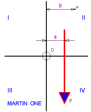
Represents a downward force P lying on an infinite vertical plane. The line of action of the force can extend to infinity in either/ or both up and down directions, and the terminal arrow can lie anywhere without affecting the magnitude. Without a reference point and a reference direction in the plane the location of the line of action is undefined, and even more important the moment, a very important physical parameter is unknown.
The simplest choice for a reference direction is a line parallel to the line of action lying at some arbitrary distance. This line or axis chosen is at distance of a units measured perpendicular to the line of action. A second axis is chosen passing through an arbitrary point O on the first axis and perpendicular (orthogonal) to it. By inspection (that is mental perception) the moment of the force at O is Pa units clockwise. Similarly at Q the moment is P(b-a) units counterclockwise. Obviously moment of P at all points lying to the right is counterclockwise, to the left clockwise.
The parameters force and its moment play a crucial role in the evaluation of equilibrium of useful mechanical systems.
MARTIN TWO
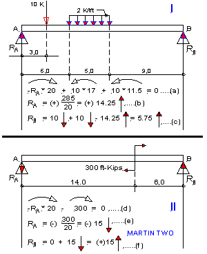
Pictures two horizontal beams supported on hinges at points A and B. The hinges are capable of generating reactive forces in any direction (i.e. 0 - 360 ) passing through the hinge point to support applied external loads.
Beam I on the top half carries a concentrated load of 10 Kips (10,000 #) and load of 10 Kips (10,000 #) uniformly distributed over a length of 5.0 ft, at distances 3.0 ft and 6.0 ft respectively. Reactions RA and RB are to be determined. By inspection it is clear that RA and RB , to balance vertical downward applied forces must be vertically upward. In II the conclusion is not so clear, however, as it is known that this couple must be balanced by a pair of equal and opposite forces with a 20.0 ft horizontal arm acting at A and B, a vertical line of action will be required. Then RA must be downward, RB upward.
In framing equations of equilibrium whose sum must vanish, it is necessary that all numbers be preceded by appropriate positive or negative signs. When working intuitively (that is, if possible) it is sufficient, in this instance, to assume counterclockwise moment positive, clockwise negative. (Note however, assumption of positive clockwise moment is equally acceptable.)
With the above assumption, equation (a) is framed and RA is solved in (b) as (+)14.25. The resultant positive sign of RA signifies that it is directed upward, for the assumed clockwise moment in (a) for RA is generated only if the force is directed upward. (This is more succinctly explained by the "Law of Algebraic Signs" which says that if the resultant sign of an unknown parameter computed from an expression which vanishes is positive then the initial assumption is valid, otherwise (i.e. if negative) the assumption has to be reversed).
It is interesting to reverse the initial assumption and use positive clockwise moment. Clearly all signs of (a) reverse, (b) remains unchanged and RA is still (+)14.25, that is by the law of algebraic signs it is still upward.
In II, equation (d) is framed by assuming vertically upward RA (it generates clockwise moment about B) and in (e) RA is solved as (-)15, i.e. the assumed direction must now be reversed to point downward.
RB , in both and (e) is solved completely intuitively, i.e. simply by considering the known directions, and forgoing assumption of a positive direction. In this instance the law of algebraic signs does not apply, for the equations do not vanish.
The formal equation assuming positive vertical upward direction will be as follows:
RB + 14.25 - 10 - 10 = 0 .. or RB = (+)5.75 ↑
Most problems in Mechanics however, cannot be handled by inspection, the solution requires the rigorous discipline of an assumed coordinate system, and computation of moments needs the cross product rule modified by eliminating the concept of the vector normal to the coordinate plane.
MARTIN THREE
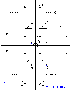
Reproduces four sections of the infinite plane shown in Martin One. To illustrate the four possible coordinate systems without drawing four separate sketches the positive quadrant of each system is shown - the origin is shifted from the true origin O to A, B, C, and D respectively retaining the relative location of force P. It is emphasized that in each case I, II, III, and IV, only positive X and Y axes are shown. Associating unit vectors i and j with X and Y axes respectively, the cross products are formed for each case. Note that the radius vector ai precedes the force vector Pj in each case. I is the X, Y axes of the left-hand, II of right-hand (see www.euclideanspace.com/maths/geometry/coordinatesystems/cartesian) system, III a system popularized by Timoshenko (see "Mechanics of Materials", Timoshenko and Gere). Obviously in II, III the cross product is (-)Pa, while in I, IV it is (+)Pa, inspite of the unassailable observation that the moment is clockwise in every instance. This establishes that the algebraic sign depends on the coordinate system - but the question remains how and why?
Before answering the question posed above, that is correlate geometry and mechanics, it is necessary to review Newton's first law of motion - a particle displaces in the direction of the applied action i.e. a positive force moves a particle in the positive linear direction and vice-versa - which requires that a positive force be directed in the positive direction of the coordinate axis, for, then and then only displacement occurs in the positive linear direction. It may then be logically inferred that a positive couple (see II Martin Two) must displace a particle along a positive arc around the origin and vice versa - i.e. physically a clockwise couple or the clockwise moment of a force about the origin must produce a clockwise rotation.
Then to answer the question the property of positive rotation in any coordinate system must be sought.
MARTIN FOUR
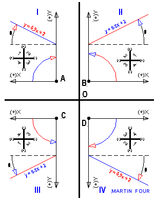
Is a reproduction of Martin Three without the vectors. The property sought will be established by logical inference.
In each case the straight line y = 0.5x + 2 is plotted. The slope-intercept form of the straight line equation presumes that y is the dependent, while x is the independent variable; 0.5 is the slope of the line which must lie either in the first or the third quadrant (see four quadrants marked in each case). However, by assumption both x and y being positive as shown the quadrant must be the first. The angle q (tanq = 0.5) is indicated in each plot, measured from the positive direction of the X (independent variable) axis varying between 0 and 2p.
It is obvious from each system that if tanq must evaluate to 0.5 then in II, III q must be measured counterclockwise while in I, IV clockwise.
It is easy to observe that in all four systems the rotation of the positive independent variable axis into the dependent variable axis through the smaller angle (that is p/2) is the positive rotation of the system - counterclockwise for II, III clockwise for I, IV.
Reverting to Martin Three it is seen that for II, III cross product is negative ( clockwise moment - counterclockwise rotation positive), I, IV positive ( clockwise moment - clockwise rotation positive).
Equations (a) and (d) in Martin Two can now be recast assuming the use of coordinate system II in Martin Three.
(a) (-)20i 3 RAj + (-)17i 3 (-)10j + (-)11.5i 3 (-)10j = 0
or (-)20RA + 170 + 115 = 0
(d) (-)20i 3 RAj + (-)300k = 0
or (-)20RA + (-)300 = 0
Note: Unknown vectors are always directed in the positive direction of the corresponding coordinate axis so that by the law of algebraic signs the computed sign is always correct.
|
Subj: |
Re: GEOMETRY MECHANICS Correlation for Dummies |
|
Date: |
3/24/03 5:16:39 AM Eastern Standard Time |
|
From: |
martin |
|
To: |
Subhash |
|
Sent from the Internet (Details) |
|
March 24, 2003 Martin, my responses are in BLUE Subhash
Subhash,
Thank you very much for this, here are some first thoughts.
I would help me to have a statement of the objective of the paper at the
beginning, Is it show
ways to derive geometry information such as a
coordinate system from a given mechanical system?
Yes, then use the geometrical system to compute unknown vectors(Force,
couple, Moment), and tensors (most important stresses)
Martin 1
It seems to me that this requires two
points and one direction to define the coordinate system, the point O and the
starting point and direction of the force?
I may not have been quite clear in my language - may be some editing is necessary.
However here are my thoughts. In this sketch, the only information I have is
the line of action of a force and the terminal arrow and another point about
which moment has to be evaluated. I will give you an example from land surveying.
A point on the ground P1 is marked by a stake (terminal arrow of force). I am told that the line of action of the force is parallel to the magnetic north. A second point P2 is also marked somewhere else on the ground.
What do I do? I shoot the magnetic North, mark it on the ground,
then proceed to P2 and shoot an orthogonal line, by some means, to intersect
the line of action. All I need to do is measure the distance from P2
to the intersection point. I do not need the origin O.
I hope the write up (word document) makes it clear.
This is as far as I have got so far, but one other point, what audience is
the document aimed at (apart from me - which would explain the '
for Dummies' at the end of the title!) If
it is aimed at an international
audience would it be better to use SI units.
My audience, initially, is my compatriots
in India (may be Pakistan and Bangladesh too but I do not have too much experience
of these two countries). Your website is my target for the purposes of useful
comments and correction of errors. May be I am all wet in my ideas, may be I
am all wrong. Transforming data to SI units is simple and I can do it whenever
you want.
Martin
Subhash,
I have put a html version of your document here (just for our own use to see
what it looks like in html) I wont link to it from the other pages until you
are happy with it.
https://www.euclideanspace.com/maths/geometry/coordinatesystems/cartesian/subhash/
other comments/questions below:
>> It seems to me that this requires two points and one direction to
>> define the coordinate system, the point O and the starting point
>> and direction of the force?
> I may not have been quite clear in my language - may be some
> editing is necessary. However here are my thoughts. In this
> sketch, the only information I have is the line of action of a force
> and the terminal arrow and another point about which moment
> has to be evaluated. I will give you an example from land surveying.
> A point on the ground P1 is marked by a stake (terminal arrow of force).
> I am told that the line of action of the force is parallel to the magnetic
> north. A second point P2 is also marked somewhere else on the ground.
> What do I do? I shoot the magnetic North, mark it on the ground, then
> proceed to P2 and shoot an orthogonal line, by some means, to
> intersect the line of action. All I need to do is measure the distance
> from P2 to the intersection point. I do not need the origin O.
> I hope the write up (word document) makes it clear.
Yes, think it would help to make it a bit clearer about what we are trying
to do. I think what you are saying is, to define a moment we need:
1) a point Q about which to measure the moment.
2) a force, defined by its starting point, direction and magnitude.
What I was thinking about was how to define the coordinate system, for this
we could use,
1) the origin O.
2) another point and direction, in this case given by the starting point and
direction of the force.
So are we saying that we can define a moment without fully defining a
coordinate system? We seem to be saying that we need some means to get a
reference direction, but no need to know an origin of the coordinate system.
> My audience, initially, is my compatriots in India (may be Pakistan and
> Bangladesh too but I do not have too much experience of these two
> countries). Your website is my target for the purposes of useful comments
> and correction of errors. May be I am all wet in my ideas, may be I am
all
> wrong. Transforming data to SI units is simple and I can do it whenever
you
> want.
Yes, at some stage, it would be good to convert to SI units.
Martin
Subj:
response dated 3/25/03
Date: 3/25/03 5:11:36 AM Eastern Standard Time
From: Martin
To: Subhash
Sent from the Internet (Details)
10 point black and 14
point Red Martin
14
point blue Subhash
Subhash,
I have put a html version of your document here (just for our own use to see
what it looks like in html) I wont link to it from the other pages until
you
are
happy with it (Looks
good to me).
https://www.euclideanspace.com/maths/geometry/coordinatesystems/cartesian/subhash/
other comments/questions below:
Yes, think it would help to make it a bit clearer about what we are trying
to do. I think what you are saying is, to define a moment we need:
1)
a point Q about which to measure the moment.
2) a force, defined by its starting point, direction and magnitude.
Let
us reverse the order since force is the principal parameter.
1) a force ..... etc
2) a point Q ... etc
What I was thinking about was how to define the coordinate
system,
for this
we could use,
1) the origin O.
2) another point and direction, in this case given by the starting point and
direction of the force.
When
evaluations occur intuitively (brain power) a coordinate system is not required.
Hopefully I have explained this in Martin 2. The counterclockwise arrows over
expresssions (10 * 17) and (10 * 11.5) are intuitive. The discipline of a coordinate
system and cross product rule is not essential unless the mechanical system
is complicated. I have umpteen examples of many complex systems.
So
are we saying that we can define a moment without fully defining a
coordinate system? We seem to be saying that we need some means to get
a
reference direction, but no need to know an origin of the coordinate system.
True.
As pointed out above a coordinate system is needed for the solution of a complicated
mechanical system.
Yes,
at some stage, it would be good to convert to SI units.
I
agree.
Martin
Subhash
Please
send me any improvements to here.
I would appreciate ideas to make the pages more useful including error correction,
ideas for new pages, improvements to wording. It helps if you quote the full
URL of the page.